Phase2 UI: Instructions for FRODOSpec
Introduction
FRODOSpec observations usually consist of two phases:
- Slew and acquisition using an imager (usually IO:O) to place the target on the FRODOSpec fibre bundle.
- A sequence of FRODOSpec instrument configurations and exposures to obtain the data.
For the first phase in the above list an imager is used to identify and acquire the target. In almost all cases, IO:O will be used as the acquisition camera. A sequence of images is taken and EITHER a WCS fit is applied to the images so that the target can be moved onto a "magic" pixel on the IO:O CCD, OR the brightest target in the imager field is moved on to the magic pixel. Once the target is acquired in this way, a tertiary mirror is deployed so that the telescope beam is redirected toward the FRODOspec fibre bundle. FRODOspec is then configured so that spectroscopic data may be acquired - step 2 above.
FRODOspec observes red and blue spectra simultaneously. To accomplish this, the dual beam spectrograph operates as two independent instruments, with a red arm and a blue arm running in parallel. Users must send separate instrument configuration commands and exposure commands to each arm.
In almost all cases, the sequence of instrument configurations and observations needed to acquire FRODOspec data should be defined using the phase 2 "Wizard". Use of the Wizard should also ensure that the instrument is correctly configure for synchronised red and blue-arm observing.
The Basic Wizard Sequence

FIG.1. The FRODOspec Instrument Config Creation Window. (Click to enlarge.)
The Wizard guides users through the steps needed to acquire a target using IO:O (or one of the LT's other imagers), and then obtain the data needed for fully-reduced red and blue spectra.
To create an observing "group", with the proposal highlighted in the main phase2 window, click on the Create a Group button top-right to insert timing and observing constraints. Check out the Phase 1 web-page if you are not sure about the meaning of the various timing constraints. The new group will appear as an item "within" the proposal in the main window. Highlight this group and select Create New Observing Sequence. From the subsequent pop-up select the Wizard for FRODOspec (Dual Beam Spectrograph) option and click Continue.
In the (Create) Dual-Beam Spectrograph Sequence Wizard window users can select an existing Target (or add a new target to the list available to the programme); choose a Rotator setting (discussed below) - most people will use Automatic (Cardinal); select the acquisition mode (WCS or BRIGHTEST, discussed below) - users may also choose to allow use of an alternative acquisition instrument here (discussed below); and set the Autoguider to Yes, Off or On-if-available.
To generate an observing sequence, users must populate the Red Arm and Blue Arm Observing Sequence boxes by clicking on the Config, Expose and Arc buttons to the right of each box. However, if separate red and blue arm configs don't yet exist for this programme, these need to be created first.
Creating New Instrument Configs
If you have not previously used FRODOspec you will need to create new red-arm and blue-arm configs. Once this pair of configs has been created they become available to all proposals in the same programme and can simply be re-used without creating new ones every time.
To create new configs, click on the Create button (labelled 'Create Instrument Configuration') in the (Create) Dual-Beam Spectrograph Sequence Wizard window. In the Instrument Config Creation window (shown right), enter a meaningful Instrument Config Name, select FRODO_RED or FRODO_BLUE for the instrument name, and select the grating to be used - either HIGH_RESOLUTION (for the VPH grating) or LOW_RESOLUTION for the lower-res grating. Click Create to generate this new red-arm config, and repeat the process to create an equivalent blue-arm config. Both configs are now available to select from the FRODOspec wizard for use with this or any other group in your programme.
Producing an Observing Sequence
You are now ready to add the necessary steps to your Sequence of observations. From the (Create) Dual-Beam Spectrograph Sequence Wizard window (shown below), click on the Config buttons to add the red and blue configurations you've just created to the red and blue arm sequences, the Expose buttons to define the duration and number of spectroscopy exposures in each arm, and the Arc buttons to add a final arc spectrum to the end of each sequence. A simple observing sequence should look something like this:
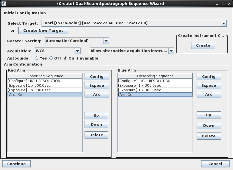
FIG.2. The FRODOspec Sequence wizard after selection of an instrument config, a number of exposures x exposure time (entered twice), and an Arc. Note how both arms of the instrument match. In this example two single 300 sec exposures are requested; the two [Exposure] rows could be replaced with a single row specifying 2 x 300 sec. (Click to enlarge.)
Click Continue to add the sequence to the group you are creating. The system will display the observation sequence in its entirety (if necessary, click on the button to the left of [BRANCH] to unfold these rows). You will note that autoguider and other mandatory configuration commands have been added automatically above the exposures you specified.
Click Continue again to proceed. In the main Phase2 window (with the new group highlighted) the Create New Observing Sequence button bottom-right is replaced with buttons which allow you to display, edit, or even delete the observing sequence associated with the group. If you display the sequence it should look something like this:

FIG.3. A typical FRODOspec wizard sequence (click to enlarge).
The above sequence contains the following steps:
- SLEW: Slew to target; only one target is possible per group when using the wizard. Here the cassegrain derotator is set to one of the four cardinal angles.
- FOCAL PLANE: Set for IO:O since this is the acquisition imager being used. (This sets the nominal centre of the focal plane pointing model.)
- FINE TUNE: Configure IO:O for imaging acquisition, in this case using WCS_FIT mode. Execute the acquisition.
- DUAL BEAM SPECTROGRAPH CONFIG: Configure FRODOspec.
- AUTOGUIDER CONFIG: Acquire a guide star and switch on the autoguider (if requested).
- BRANCH: Set up the two parallel FRODOspec configuration branches for the red and blue arms.
- ITERATOR: repeat the sequence of exposures within the iterator NN times
- DUAL BEAM SPECTROGRAPH CONFIG: Configure the individual red and blue arms.
- EXPOSE: Obtain a 300 sec spectrum
- EXPOSE: Obtain a 300 sec spectrum
- ARC: Obtain a Xenon arc spectrum.
- AUTOGUIDER CONFIG: Switch the autoguider off.
In the above example the two 1 x 300 sec exposures could be replaced with a single [Exposure](Multrun) line set to 2 x 300 sec; both would do the same thing. Regardless of how the two exposures are sequenced, the red and blue arm sequences should still match, i.e. they should have the same number of exposures with the same exposure times. This ensures synchronised operation of the instrument.
To perform any tasks beyond this standard set of configurations and observations (e.g. a second exposure of an offset sky field) you must use the general Sequence Builder. For complicated groups it is HIGHLY RECOMMENDED that you first use the wizard to get the basic sequence structure established and then edit this sequence. Users are recommended to contact LT Phase 2 support if they require observations that can not be generated simply with the Wizard.
Further Details
Acquisition
Select whether the telescope pointing should be fine-tuned to place the target on the IFU using a WCS astrometric fit or simply by centring up on the BRIGHTEST source.
WCS acquisition is frequently ineffective for targets brighter than 8th mag. BRIGHTEST acquisition requires that your target is the brightest object within one full field-of-view of the acquisition camera (10 arcmin for IO:O). See FrodoSpec acquisition for more details. You must use J2000 co-ordinates for WCS acquisition and the position must be accurate to 2 arcsec to ensure the target will be on the IFU. Depending on the provenance of the original catalogue it is quite common for coordinates in on-line databases such as SIMBAD to be insufficient. If you do not already have recent astrometry consider checking it with a brief snapshot image of your field first before investing your time allocation in long FRODO integrations.
The default and recommended choice of camera for acquisition with FRODOspec is the primary science imager, which is currently IO:O. Other instruments - for example, RISE or SPRAT - could be used as the acquisition camera in certain circumstances (e.g. if IO:O is off-line, or if a smaller field-of-view would help with BRIGHTEST acquisition). Please contact us if you think using anything other than IO:O may be necessary for your observations.
Rotator Setting
The cassegrain rotator (or strictly speaking 'de-rotator', since it corrects the rotated sky), sets how the image is orientated with respect to equatorial North and East. Two options are available to users, AUTOMATIC or MANUAL.
- AUTOMATIC orients the cassegrain derotator so that the acquisition image will be aligned with one of the 'Cardinal' sky orientations N, E, S or W. Note, however, that users cannot control which of the four is selected. The system automatically chooses the field orientation best placed at the time of the observation to give the longest available observation duration without encountering the rotator axis limits. Furthermore, the rotator is not moved after acquisition. This means that the sky position angle in the IFU image reconstruction will not match the acquisition image; it is actually rotated by about 45 deg.
- MANUAL allows users to explicitly set the field orientation, either as a sky position angle or as the mechanical mount angle of the cassegrain derotator. With MANUAL selected, after creating an exposure, simply click "Continue" and the wizard will take you to the rotator specification screen.
In most cases we suggest leaving the Rotator set to AUTOMATIC, unless your sequence is longer than a couple of hours in duration. In such cases a specific angle may need to be defined so that the cassegrain rotator limit is not reached before the end of the observation. For a detailed discussion, please read the Cassegrain Rotator guide and contact LT Phase 2 support for assistance if you are not 100% sure what you are doing!
Autoguiding
Users may choose to observe with or without guiding. Note that if Autoguiding=YES (On) is selected, an observation will only be attempted if a guide star is available. If auto-guiding is set to On if available, observations will be attempted regardless of whether the telescope is guiding or not. See the Sequence Builder web page for further details.
Defocus
The system automatically applies all offsets required to keep the instruments and filters in focus. Users should only explicitly apply a DEFOCUS value when they want their spectroscopy data to be defocused! Saturation with FRODOspec is unlikely, so applying a focus offset would be extremely unusual. If it is necessary, we generally recommend using +ve DEFOCUS values. See the Sequence Builder and FRODOspec web pages for further details.
Please end your observation sequence with "Non-cumulative defocus = 0" so you leave the telescope in focus for the next observer.
Red and Blue Arm Configurations
The two branches defined in an observing sequence (see Fig.3 above) contain the sequence of tasks to be performed by the two instrument arms. The sequences run in parallel with only a moderate degree of synchronisation between them. Each branch may contain any number of instrument configurations, on-sky exposures, and arc exposures. However, the sequence must include at least one instrument configuration command which must appear before any exposures. The branch may subsequently contain none or any number of config, expose, and arc commands. The commands will be issued in the order defined; the order may be modified by selecting an item and using the "Up" and "Down" buttons in the Sequence Wizard (Fig.2) or when editing an observation (see 'Using the Sequence Builder', below).
We generally recommend that users keep the sequences in the two arms as similar as possible so that the automatic interlocking of the arcs (discussed below) may be performed efficiently. For example, it is technically possible to have an Arc followed by an Exposure on the red arm, and an Exposure followed by Arc on the blue arm - but this would take considerably longer to execute. Arc should usually be placed at either the start or the end of both branches.
Arm Synchronisation
The two FRODOspec arms are not automatically synchronised; each branch in the observing sequence simply executes its list of tasks in direct sequence. It is therefore important that users ensure that the two arms match as closely as possible in terms of number and duration of exposures.
Users must send separate instrument configuration and exposure commands to the two arms in FRODOspec. Note how the control flow in a FRODOspec sequence (Fig.3) splits into two branches, one for each arm. The configs and exposures in each branch are executed independently. The two control branches do, however, automatically interlock each other so that if one arm is obtaining an arc, the other will not attempt to start a science integration until the arc lamp has been switched off. Similarly, if the two arms are performing integrations of unequal duration followed by an arc, the arm with the shorter integration will wait for the other arm to complete before switching on the arc lamps. One consequence of this is that users should attempt to keep the total (integration + overhead) times on the two arms equal. If, for example, a target requires 600 sec with the blue arm but only 300 sec with the red, 2 x 280 sec could be used on the red arm (given the readout overhead is 20 seconds) so that both arms complete their sequences at roughly the same time.
When both branches are complete, the control flow recombines and proceeds with any further commands in the sequence. This might be another target (e.g., offset to blank sky) or an instrument change. Remember that the FRODOSpec acquisition process will have specified an 'aperture' that places the target on the fibre IFU. If an image is required after FRODOspec spectra have been obtained, it is preferable to include a "Slew" and a "Focal Plane" command in the sequence in order to move the target back on to the centre of the imager being used.
Arc Spectra and Wavelength Calibration
FRODOSpec is a bench mounted spectrometer and is therefore mechanically very stable. Since there is no flexure as the telescope tracks there is no need to obtain repeated arcs throughout a long observation sequence. We suggest obtaining new arcs no more than once for each grating reconfiguration and in most cases a single arc exposure at the end of the observation sequence is all that is required. We recommend using only the Xe arc lamp; the exposure time will be set automatically. The FRODOSpec web pages include a Xe arc atlas.
There is generally no need to include tungsten lamp flats in the observation sequence. A set of tungsten (W) lamp continuum spectrum flat fields are obtained automatically every night and archived. These W lamp flats are used by the level 2 reduction pipeline to trace and extract the fibres. If you wish to perform your own extraction (and not use the LT's level 2 reduction products), please contact us and we can make the nightly tungsten lamp observations available to you.
Using the Sequence Builder
Setting up a FRODOSpec group from scratch is not simple and if you are attempting to create a more complicated sequence than is possible using the wizard then it is suggested that you still use the wizard to create the framework of a standard FrodoSpec group and then edit that sequence to add your extra requirements. See the Sequence Builder web-page for a general description and the Sequence Builder Tutorial for a FRODOSpec specific "walk-through".
Below we list a number of issues that users should consider when editing a FRODOspec sequence.
Acquisition
A FrodoSpec acquisition sequence should ALWAYS include the following commands. These are needed to accurately place the target on the IFU fibre bundle:
- SLEW moves the telescope optical axis to the target position - simple blind pointing based on the telescope pointing model.
- FOCAL PLANE should be set to the acquisition camera (typically IO:O), not to FRODOspec. This applies blind offsets to the telescope so that the target lies in the focal plane at approximately the optimum position for the nominated acquisition camera.
- FINE TUNE iteratively obtains exposures with the acquisition camera in order to move the target precisely onto the IFU fibre bundle.
See Fig.3 above for an example of how these three steps should appear in a sequence.
Observing Two Targets from the Same Group
Users may wish to observe a spectro-photometric standard directly before or after their science target. This is possible by repeating exactly the same steps needed to observe one target (as defined by the Wizard), and is described in the SPRAT phase2UI guide.
Combining spectroscopy and imaging in a single group
It is possible to precede or follow a sequence of FRODOspec configs and exposures with a sequence of IO:O images (see below). Note, however, that the FRODOSpec acquisition process will have specified an 'aperture' that places the target on the fibre IFU. If an image is required after FRODOspec spectra have been obtained, it may be preferable to include a "Slew" and a "Focal Plane" command in the sequence to move the target back on to the field-of-view centre of the imager being used. Alternatively, users may prefer to ignore the fact that the target may be offset from the imager field centre, since excluding a second "Slew" and "Focal Plane" command in the sequence would reduce overheads by a few minutes.
Autoguider
The telescope hardware must be reconfigured for FRODOSpec after the acquisition process but before the autoguider is engaged. Users should therefore ensure that a FRODOspec instrument configuration (any legal FRODOspec configuration is fine) appears after the acquisition and before any AUTOGUIDE command. Specifying the FRODOspec instrument configurations to be used later is still necessary within the two arm branches (see Fig.3).
After the FRODOspec observations are complete the autoguider should be switched OFF before moving to another spectroscopic target acquisition within the same group. However, the guider can be left ON if the same target is to be observed with a different instrument.
Finally, remember that the autoguider may be set to OFF, ON ("Yes"), or "On if available". When set to "On if available", guiding will be attempted but if it fails for any reason the group will continue without it. When set to "Yes" (ON), then failure to lock the autoguider is an error and the entire group would be aborted.
Calibrators
Bias and Darks. There is generally no need to obtain bias or dark frames. If you do so then they will not be used by the automated data reduction pipelines.
Spectral Arcs. Any Xe arcs you obtain will be used by the automated pipeline. Since FRODOSpec is bench mounted and does not move with the telescope we do not suggest taking any more than one arc per instrumental hardware reconfiguration. For example if you observe a target and an offset sky, a single arc frame will suffice to reduce both. We do not recommend use of any arcs other than Xe. In order to avoid arc exposures interfering with autoguding, we recommend that arcs should be obtained after (not before) science exposures.
Sky Subtraction. The 10x10 arcsec field of view of the IFU is adequate to allow sky subtraction of point sources in a manner similar to long slit spectroscopy. For extended sources comparable in size or larger than the IFU you might want to include an offset field to use for sky subtraction. This offset sky will not be automatically applied by the data reduction pipelines; you would need to do this sky subtraction yourself.
An example
The following is an example of a complex FRODOSpec group illustrating many of the points discussed above. The sequence obtains spectra of a target, spectra of an offset field (note the second FRODOSpec BRANCH), and then swaps to an imager - in this case, the retired CCD camera RATCam - to obtain multicolour photometry of the same field.
The sequence editor allows for a great degree of flexibility when creating or editing existing groups. For example, in the sequence below a user might prefer to obtain the RATCam images before the FRODOspec spectra. This would actually be slightly more efficient in terms of instrument switches because the acquisition uses RATCam anyway. (This example was created when RATCam was the primary imager; every instance of RATCam here can simply be substituted by IO:O with no further complications.)
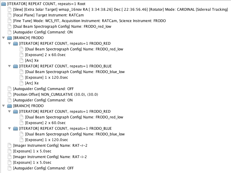
FIG.4. An example of a more complex FRODOSpec sequence. (Click to enlarge.)
Points to note:
- The telescope is slewed and a WCS acquisition performed
- Instrument configuration is switched to FRODO before the autoguider is engaged. In reality we would probably not bother with auto-guiding on integrations as short as these.
- Each branch starts with a config command.
- We obtain 2x60sec on the red arm even though it is not really required. If we entered 1x60sec, the red arm would be sitting idle for a minute whilst waiting for the 120sec blue integration to complete.
- Switch off the autoguider before moving the telescope. Presumably we have previously determined that this offset gives a good blank sky.
- Re-engage the autoguider
- Each BRANCH must still start with a config command even though we are not changing instruments.
- There is no real need for another arc since we have not moved the grating since our previous one.
- We obtain r and i band images of our field with RATCam.
- Finally, we switch off the autoguider.