

IO:O
Contents
- Introduction
- Current Status
- Specification
- Filters
- Standards
- Sensitivity and Saturation
- Observing Overheads
- Shutter Effects and Precision Timing
- RTML and Automated Followup
- Data Processing Details
- Dates of Hardware Changes
Introduction
IO:O is the optical imaging component of the IO (Infrared-Optical) suite of instruments, and is a replacement for RATCam that has been the workhorse optical camera for many years. It provides a wider field of view and greater sensitivity than RATCam, and when combined with IO:I may eventually allow the ability to almost simultaneously image in both optical and near-infrared bands.
Current Status
ONLINE
IO:O was originally equipped with a Fairchild 486 CCD detector. However, this was found to have degraded during storage resulting in poor blue Quantum Efficiency (QE), so it was therefore replaced in June 2012 with an e2V CCD 231-84. This has worked well giving broadly similar performance to RATCam but with the advantage of a wider field of view. Read noise is currently slightly higher than RATCam with QE tilted more towards the red end of the spectrum. At present a single readout mode is implemented, giving a total readout and file creation overhead of 18.5 seconds per image (2x2 binned). 1x1 binning is also available, although we do not regularly obtain 1x1 flats. Please contact the LT Support Astronomer if you wish to use this mode.
Specifications
IO:O's principal observational specifications are listed below.
| Detector | 4096x4112 pixel e2v CCD 231, deep depletion, Astro ER1 coated | ||||||||||||
| Pixel size | 15.0 x 15.0 microns | ||||||||||||
| Pixel scale | approx. 0.15 arcsec/pixel (unbinned) | ||||||||||||
| Field of view | 10 x 10 arcmin | ||||||||||||
| Read noise | ∼ 16 electrons Check FITS header for value at time data were obtained. |
||||||||||||
| Dark current | < 0.002 e / pix / sec (unbinned, 263K) ~ 0.01 e / pix / sec (unbinned, 273K) |
||||||||||||
| Binning | 1x1 and 2x2 | ||||||||||||
| Readout time1 | ~37 sec (1x1 binned), ~13.5 sec (2x2 binned) Overhead between exposures is slightly longer. |
||||||||||||
| Windowed modes | Not currently available | ||||||||||||
| Bad pixels | 6 dark point defects; 2 hot pixels; 1 column defect. (pixel mask) | ||||||||||||
| Gain (1x1) | 1.6 electron / ADU | ||||||||||||
| Gain (2x2) | 1.6 electron / ADU | ||||||||||||
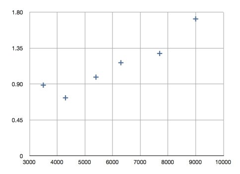
| Quantum Efficiency (figures supplied by manufacturer) |
|
1Note: the readout time alone is not the overhead between
consecutive exposures,
even when taken with the same filter - see below.
Filters
IO:O has two filter selection mechanisms:
- a 12-position filter wheel for Sloan, Bessell and Hα filters
- a pair of slide mechanisms housing neutral density (ND) filters
An exposure may use any single position of the filter wheel, and either or both of the NDs.
Filter Wheel: Sloan, Bessell, Hα filters
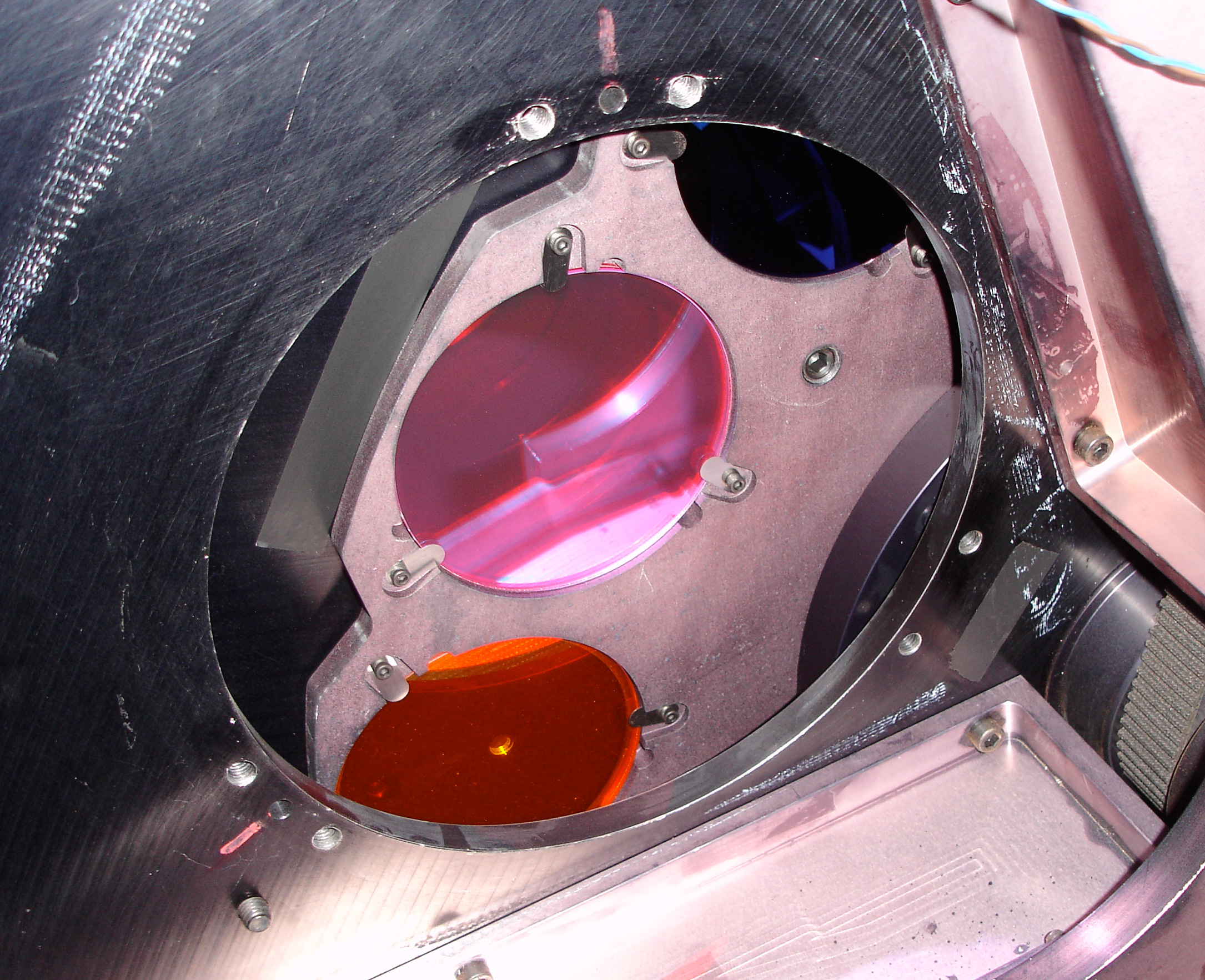
IO:O filter wheel aperture © S. Bates
The wheel is mounted outside the instrument; the IO:O dewar attaches to a plate below the wheel. The wheel contains a selection of Sloan (u',g',r',i',z'), Bessell (B and V) and narrow-band filters (Hα rest wavelength and Hα redshifted to 663.4nm, 670.5nm, 675.5 nm and 682.2 nm).
The Hα 682.2nm filter
Being the least-requested filter, the Hα 682.2 nm slot has been used intermittently to test alternative instrument configurations. See Dates of Hardware Changes for historical information. As of 16th Jan 2024, Hα 682.2 nm has been removed indefinitely and replaced by a CN filter. If you require this filter, contact the support astronomer to discuss the current status.
Filter Slides: Neutral Density filters
Two absorptive neutral density (ND) filters were added to the IO:O filter set in 2013. They are mounted outside the filter wheel on a mechanism that can slide one or both filters into the beam. The ND filters can therefore be used in combination with those in the filter wheel.
The ND filters were installed specifically for obtaining pictures of the Moon and bright planets for the National Schools' Observatory. They have not been characterised for colour terms — despite the name their transmittance profiles are not perfectly flat — nor are any regular flat fields taken. The ND filters are nonetheless available to professional users if they wish to use them, but they must contact us ahead of time. They can be selected in the Phase2UI for regular observations but cannot be used for IO:O acquisition onto the spectrographs SPRAT, FRODOSpec or LOTUS.
| Filter | Optical Density |
Visual Band Transmittance (%) |
Visual Band Extinction (mag) |
|---|---|---|---|
| ND1.5 (Schott NG4) |
1.5 | 3.16 | 3.75 |
| ND3 (Schott NG3) |
3.0 | 0.10 | 7.50 |
| combined ND1.5+ND3 |
4.5 (effective) |
3.16×10⁻³ | 11.25 |
Both filters are 2.9mm thick.
Filter transmittance plots
Transmittance plots for each filter are displayed below (click plots for larger versions).
Sloan
|
Bessell
|
Hα
|
CN
|
| Neutral Density | ||
| ND1.5 (200-1100nm) 
|
ND3.0 (200-1100nm) 
|
ND3.0 (400-700nm) 
|
| ND profiles from Präzisions Glas & Optik's SCHOTT-filter calculator | ||
Plain text files of most of these filter profiles are also available:
High resolution (0.5nm) interpolated curves for all the broad-band filters (u',g',r',i',z',B,V) along with the IO:O cryostat window and the CCD QE have been published in Liverpool Telescope Technical Note 1: Telescope and IO:O Throughput.
Standards
A standards observation programme similar to that previously used with
RATCam is in operation. Broad-band images of calibration fields drawn
from the SDSS Extended
Northern+Equatorial u'g'r'i'z' Standards are obtained every 2-3
hours. They are spaced every few
hours of RA and are observed in all bands on photometric nights, and in r' & i' on non-photometric nights to autonomously monitor the seeing.
These data are available to all observers via the LT data
archive under the Proposal ID
IOOStand or, for observations obtained within the
past month, from the Recent
Data page.
If you require standards beyond those routinely taken by the robotic system, you must request them explicitly in your Phase 1 proposal and include the appropriate observations in your Phase 2 sequence definition. The time needed for these observations should also be included in your application.
Sensitivity & Saturation
Our Exposure Time Calculator should be used to estimate exposure times to be used with IO:O.
IO:O replaced RATCam as the work-horse optical imager at the LT in late 2013. The relative sensitivity of the two instruments is plotted below, where the X axis is Wavelength in Angstroms and the Y axis the relative photon count rate for IO:O divided by the photon count rate for RATCam. This plot demonstrates that the e2V detector in IO:O appears to be slightly worse in the blue though considerably better in the red than the detector in RATCam.
In terms of IO:O's saturation limit, an r~12 star will saturate the detector in 10 seconds under the best seeing conditions typically observed at ORM. Users with targets brighter than 12th mag should consider defocusing the telescope.
Observing Overheads
To the calculated exposure time (Te) and the group initialisation time (Ti), the following overheads must be added:
- Acquisition time, Ta - time taken to slew the telescope on target. This is 60 seconds.
- Autoguider acquisition, Tg - only if you nominate to use the autoguider. This is 45 seconds.
- Filter change time, Tf. This is 15 seconds.
- Readout time, Tr. Assume that this is 18.5 seconds for 2x2 on-chip binning. This includes 5 seconds at the start of each exposure when FITS header information is sent from the telescope and written to the file header. Please contact us if you are interested in using unbinned mode.
|
Example Suppose you have a programme with 21 objects which you wish to observe (guided) for 10 nights in a row, with an exposure time of 60 seconds, through three different filters: |
|
Shutter Effects and Precision Timing
The type, speed and repeatability of the shutter impacts the precision of the exposure timing both in terms of integration duration and the effective time of mid-exposure. In March 2022 the IOO shutter was upgraded from a concentric iris to a travelling curtain.

Historical information
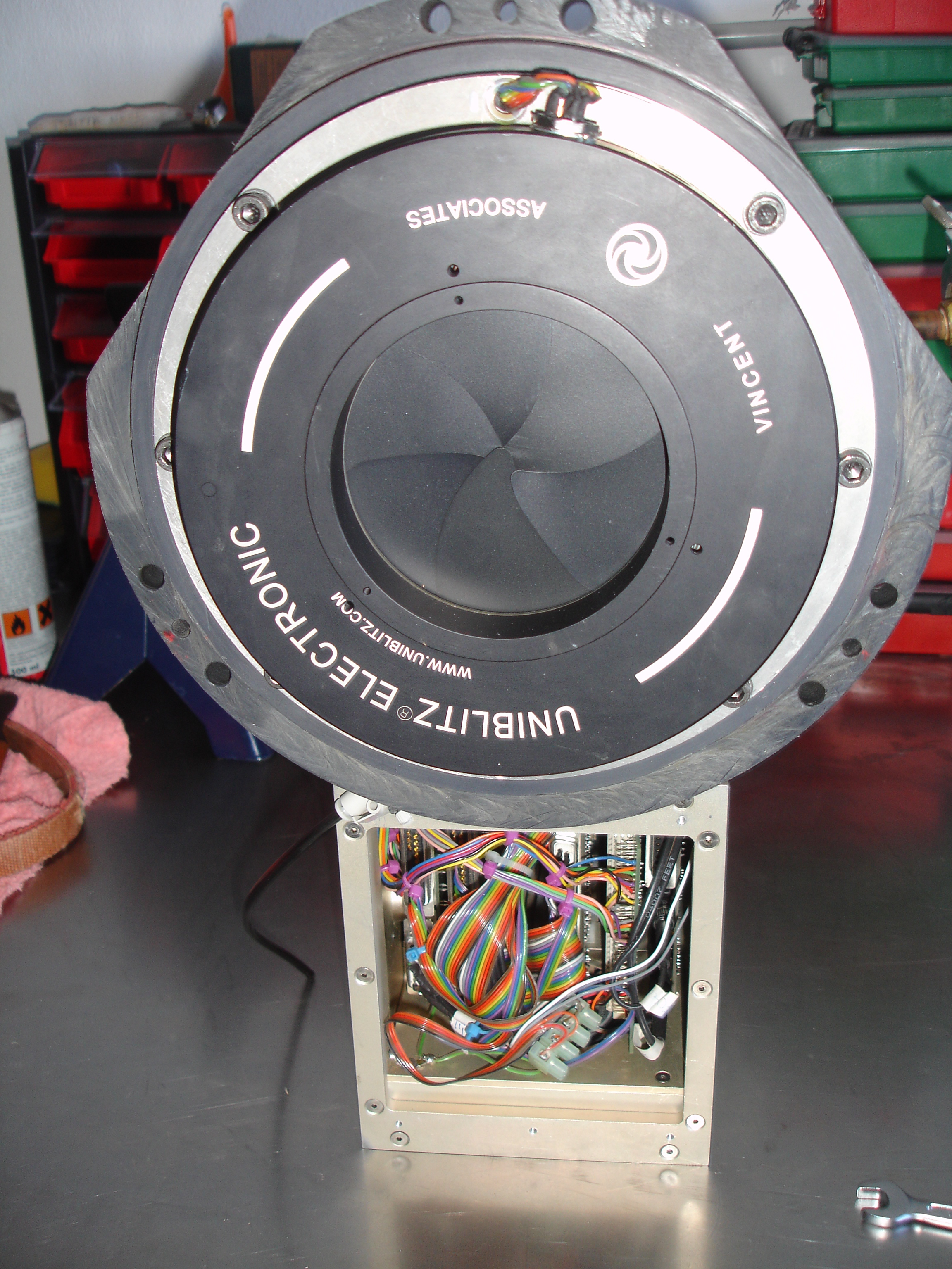
IO:O was originally equipped with a large diameter Uniblitz iris shutter. This gave a 80ms difference in exposure time between the centre and edges of the field; the integration error map at right has contours marking 20msec intervals. For reasonable photometric accuracy across the field, it was recommended exposure times should be greater than 20 seconds. It would be possible in principle to apply field-position-dependent corrections to extract photometry from shorter integrations, but this is not supported in the automated reduction pipeline.
Current information
In March 2022 we installed a Bonn Shutter which uses a pair of parallel travelling curtains (see video below) so that the entire frame receives the same total integration time. This allows accurate relative photometry from much shorter integrations. Remember however that IO:O is still not well suited to extended sequences of very short exposures due to the relatively long read-out overhead (~13.5 sec, 2x2 binned).
Duration:
- Minimum recommended exposure time = 10ms (0.01s) though it has been successfully used down to 2ms. Observers wanting to use short integration times are recommended to contact us and remember that read-out time between frames remains the same as before.
- Exposures are only controlled to an integer number of milli-seconds and true integration on sky is 0.7ms longer than you requested in phase2 and is recorded in the FITS header. For example a 10 second observation request will actually obtain a 10.0007 second integration.
Precision start and end times:
All that follows is irrelevant to most observers. You only need to consider these effects if your science requires absolute timing precision on the level of milliseconds.
- Travel time for curtain across field = 400 msec (see video below).
- Curtain travels approximately top-to-bottom and bottom-to-top, though there is a slight tilt and direction of travel is not precisely parallel to the detector edges.
- Curtain direction alternates for consecutive frames and you cannot tell which direction was used for any specific exposure.
- UTSTART time (UTC) written in header is the time the first curtain reaches frame centre; i.e. it is exposure start time at the frame centre.
- When the curtains are moving down through the frame:
- the first photons received at the top of the frame will be 200 msec earlier than the UTSTART.
- the last photons received at the bottom of the frame will be 200 msec later than the UTSTART+EXPTIME+0.7ms.
- This is reversed on alternate frames when the curtains are travelling upwards in the frame
Using IO:O
Guidelines on how to prepare observations are given in the Phase 2 web pages. Note in particular the instrument-specific User Interface Instructions. The phase 2 "Wizard" should always be used to prepare observations. Groups that can not be prepared with the wizard should be discussed with LT Phase 2 support. Note that LT staff do not routinely check observing groups, and that observing groups are potentially active as soon as they are submitted. Please do contact us if you have any questions about your observations.

RTML and Automated Followup
IO:O can accept observation requests formated in Remote Telescope Markup Language (RTML) which allows you to automatically trigger certain observations from within your own autonomous software. We provide a command line based utility which can format RTML packets for you, making it easy to integrate observing requests into a shell script or other data processing pipeline. For some use cases it might also be easier for users to upload all their observing requests from the command line instead of using the phase2ui. The facility is available to all users who have TAG-awarded time allocations. Please contact us if this sounds of interest and we can provide full user instructions.
Data Reduction Pipeline
Basic instrumental reductions are applied to all IO:O images before the data are passed to users. This includes bias subtraction, trimming of the overscan regions, and flat fielding. A library of the current calibration frames is maintained as part of the data archive and updated daily so that images are always reduced using the latest available flat-field image.
Each of the operations performed by the pipeline are described below.
-
Differential amplifier read
IO:O uses a 'dummy' read-out circuit which is identical and in parallel with the signal read-out except that it is not connected to the detector read-out register. This provides a differential reference signal to which the data signal is compared to reject common mode noise. Rather than apply the noise rejection in hardware, a 'dummy' image is stored in the raw FITS file and subtracted off by the data reduction pipeline. It thus functions effectively like a bias image taken pixel-perfect simultaneously with the image data. The differential image is linearly scaled by an empirically determined constant before subtraction in order to minimise the common mode noise in the final result. -
Bias Subtraction
Bias subtraction is based on analysis of the overscans on either side of the image. Various options exist in the pipeline software but the simplest — a single constant bias value for the entire image — has proved to be most effective and robust because any spatial structures, ramps etc have already been removed by the differential image subtraction. When multiple read-out amplifiers are being used, a single bias level is deteremined spearately for each one.
-
Overscan Trimming
The overscan regions are trimmed off the image leaving a 2048x2056 (assuming 2x2 binning) pixel image. The overscans are not included in the reduced data products.
-
Dark Subtraction
This is not currently performed though the facility exists in the reduction pipeline if required. At operating temperature (-110C) the dark current is less than 0.002 electron / pix / second which is not significant for most purposes. If you feel you need a dark frame, please contact us.
-
Flat Fielding
Twilight flats are automatically obtained every evening and morning. From five to seven frames are typically obtained, dithered on the sky, and a master flat created as a median stack of the frames. In the pipeline the appropriate master flat field is selected from the library to match the filter and binning configuration of the current exposure. The library actually holds reciprocal flat-fields normalised to unity because of the computational efficiency of multiplying rather than dividing; the image data are therefore multiplied by the library flat.
-
Bad Pixel Mask
No cosmic ray rejection or bad pixel mask is applied since it is important for users performing accurate photometry to know exactly what masking has been applied. The bad pixel masks linked below are not applied or used in any way by the pipeline but are instead made available to observers for their own use. They were generated from g',r',i',z',V twilight flat fields by flagging pixels which differ from their neighbours by more than 20%.
- 2x2 binned bad pixel mask (16KB gzipped FITS, unzips to 8MB)
-
Fringe Frames
Fringing on IO:O is weak and only detectable at all in the z' filter for very deep integrations. It is unlikely to ever be worthwhile correcting, other flat fielding residuals always being more significant.
We currently do not perform any automated defringing of CCD data. Routine checks for fringing are run by the robotic control system by taking deep integrations of blank fields in the z' filter. If you need access to the individual integrations that could be used to build master fringe frames, they are publicly available from the data archive. Simply select
IOOFringefor the Proposal ID in a search. In this way users can extract the most recent fringe frame from the archive at any time.Fringe frames for the previous Fairchild detector were obtained 9th Feb 2012. We have not published fringe frames for the new e2V detector.
- Z band: z-fringe.fits.gz - Not for data obtained after June 2012
- I band: i-fringe.fits.gz - Not for data obtained after June 2012
Fringing with the e2v chip is at a very low level and can not be seen for example in individual i band frames. A slight hint of fringing can be seen in long exposure z band frames. Given the low level, until a larger data set is obtained we can not create or distribute meaningful fringe frames.
Dates of Hardware Changes
For the benefit of observers performing long term monitoring we here summarize the dates of major hardware changes that could potentially lead to changes in photometric calibrations.
2012-05-28 - New detector
Detector array replaced with an e2V CCD 231-84. There are actually very few data in the science archive with the previous detector.
2022-03-19 - Upgraded Shutter
New travelling curtain photometric shutter installed. Minimum recommended integration time reduced from 20sec to 0.01sec. See Shutter Effects and Precision Timing.
2023-06-19 - Read-out amplifier
Prior to this date read mode was DUMMY-TOP-RIGHT. From 2023-06-19 onwards we are using DUMMY-BOTTOM-RIGHT. This means we are using a single (bottom-right) on-chip amplifier and are also simultaneously reading the dummy amplifier to allow common-mode pattern noise rejection (2014SPIE.9154E..28S).
Historical filter changes:
- 20 Oct 2014 – 24 Apr 2015: Hα redshifted to 682.2 nm was removed to make way for an uncharacterised "V+R" broad-band filter (GG475+KG3) used for tracking of the GAIA Space Telescope.
- 30 Jun – 20 Oct 2015: Hα redshifted to 682.2 nm was removed in favour of experimental polaroid.
- 16 Jan 2024: Hα redshifted to 682.2 nm has been removed indefinitely and replaced by CN.
