RINGO2
RINGO2 was decommissioned in October 2012 and recycled in part to become RINGO3, the new tri-band polarimeter. RINGO3 is now in use on the telescope; see the RINGO3 page for details. The information presented here is for historical purposes only.
Filter Set
Standards
Sensitivity
Saturation
Pipeline
Calculating Phase 1 Overheads
Phase 2 Instructions
Introduction
RINGO2 is a fast readout imaging polarimeter. It uses a rotating polaroid that rotates once per second. Unlike the original RINGO which used deviating optics to spread the time varying polarized signal into rings, RINGO2 uses a fast readout camera to capture this signal as it changes in time. Eight exposures are obtained per second synchronized with the rotation of the polaroid. Combining the eight images allows the polarization to be determined. The system uses an EMCCD, meaning that the read noise is negligible and allows combination of the frames without penalty. Fainter objects can therefore be measured by simply stacking frames.
Sensitivity
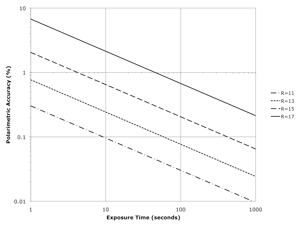
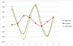
Overall the sensitivity of RINGO2 is about two magnitudes better than RINGO, as the contribution of sky noise to the measurement is much reduced in the new design. Above left is a predicted sensitivity curve, while at right are example polarization traces for the zero polarization standard star G191B2 and two polarized objects. Click images for bigger versions.
Specifications & Current Performance
| Time Resolution | Measures polarization on timescale of ~1s |
| Wavelength Range at FWHM | 460-720nm |
| Field of View | 4 x 4 arcmin |
| Filter | 3mm Schott GG475 + 2mm KG3 cemented together |
| Polarizer | Meadowlark Precision linear polarizer:
|
| Camera | Andor iXon+ 897 |
| CCD | E2V EMCCD, 512 x 512 pixels |
| Operating temperature | -60° C |
| Quantum efficiency | > 95% |
| Dark current | negligible |
| Pixel scale | 0.45"/pixel |
| Readout time | negligible |
Filter Set
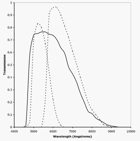
RINGO2 uses a hybrid "V+R" filter, consisting of a 3mm Schott GG475 filter cemented to a 2mm KG3 filter. The resulting bandpass curve is shown below, compared to Bessell V and R filters.

Standards
Two types of standard are necessary to reduce RINGO2 data. These are zero-polarized stars, and objects with known polarization. The zero-polarized standards are necessary to remove the instrumental polarization from the data. The polarized standards allow you to calibrate the effect of instrumental depolarization.
These standard star observations must be obtained at the same MOUNT (not SKY) position angle as the science data. In general we recommend using a MOUNT position angle of zero for all RINGO2 observations (science and standards). Calculation of a true sky position angle for your data (and hence polarization angle) is possible by using FITS keywords. In the FITS headers the sky position angle is stored in ROTSKYPA and the mechanical mount position in ROTANGLE.
Standards are spaced approximately every few hours of RA.
| Name | J2000 |
|
RA |
DEC |
|
| BDp64_106 | 00:57:36.71 |
+64° 51' 26.5" |
| BDp59_389 | 02:02:42.06 |
+60° 15' 26.5" |
| PG0231+051 | 02:33:41.00 |
+05° 18' 40.0" |
| HD25443 | 04:06:08.07 |
+62° 06' 07.0" |
| GD319 | 12:50:04.49 |
+55° 06' 02.5" |
| BDp33_2642 | 15:51:59.86 |
+32° 56' 54.8" |
| HD155197 | 17:10:15.60 |
-04° 50' 03.0" |
| HILT_960 | 20:23:28.44 |
+39° 20' 56.1" |
| VICYG12 | 20:32:40.98 |
+41° 14' 26.2" |
| BDp28_4211 | 21:51:11.07 |
+28° 51' 51.8" |
| 2331+055A | 23:33:48.00 |
+05° 46' 10.7" |
Saturation
In order to avoid saturation, which permanently degrades the response of the EMCCD, RINGO2 fields must not contain objects brighter than 8th magnitude.
Pipeline
As RINGO2 produces approximately 8 CCD frames per second (one per rotor position) it is not practical to archive or distribute the raw data from the instrument. A initial data reduction pipeline at the telescope therefore stacks all the frames at a given rotor position within a multrun and normalizes by the number of frames in the stack. A multrun of any length will therefore produce 8 files, named p_*_N_0.fits where N varies from 1 to 8. These mean stacked frames are then transferred back to the data archive at LJMU, where a dark frame is subtracted and a flat-field correction is applied. This data (P_*_N_1.fits) is then made available to users for download.
As described in the above section, two types of standard star observations (zero-polarization and polarized) are necessary to reduce RINGO2 data, which should have been obtained with the same mechanical mount position angle as the science data. The mount angle is specified in the FITS header by keyword ROTANGLE.
- Carry out sky-subtracted photometry on the frames corresponding to your zero polarized standard(s). You will have eight measurements (one per rotor position) per target.
- Carry out sky-subtracted photometry on the frames corresponding to your polarized standard(s) and science target(s)
- For each rotor position, divide the counts from the polarized standards and science targets by those from your zero-polarized standard. This process (analogous to flat-fielding) removes the effect of the instrumentatal polarization from your data.
- For each polarized standard and science target use the equations outlined in
Clarke & Neumayer 2002 to calulcate q and u,
and hence the degree of polarization (P) and position angle (PA) relative to the mount. Note that rotor
positions correspond to the nomenclature used in that paper according to the scheme:
ROTOR POSITION C & N 1 A1 2 B1 3 C1 4 D1 5 A2 6 B2 7 C2 8 D2 - Plot a graph of the observed vs actual values for the polarized standards. Place your measured value for your science target on the graph to calculate its true polarization.
IMPORTANT : Dates of hardware changes
Because the relative physical alignment between the polizer, the rotor and the CCD array is critical to the data reduction it is important to use only the correctly matched flat fields and standard stars to analyze science data. You cannot use standards before and after any hardware reconfiguration interchangably. The following list gives dates on which hardware were changed. Make sure your standards and science frames are not separated by any of these dates.
- 2010-11-10 Foreoptics changed to elliminate vignetting.
- 2011-02-15 - 2001-03-20 Drive belt broken. No data available from this time period.
- 2011-03-20 Returned to service following belt repair and filter re-seating.
- 2012-04-28 Cass bearing moved. MOUNT=0 before and after this date are not equivalent.
Calculating Phase 1 Overheads
For RINGO2 and RINGO3 a simple 60 second slew overhead is all that is required. No filter changes are possible, and the readout time is negligible.
Using RINGO2 with the Phase 2 GUI
See here for instructions on using the Phase 2 GUI to program the LT to use RINGO2:
RINGO2 Phase 2 Instructions


